• facebook
  • youtube
  • linkedin
Leave Your Message

What Is the Best COF Testing Equipment in 2026?

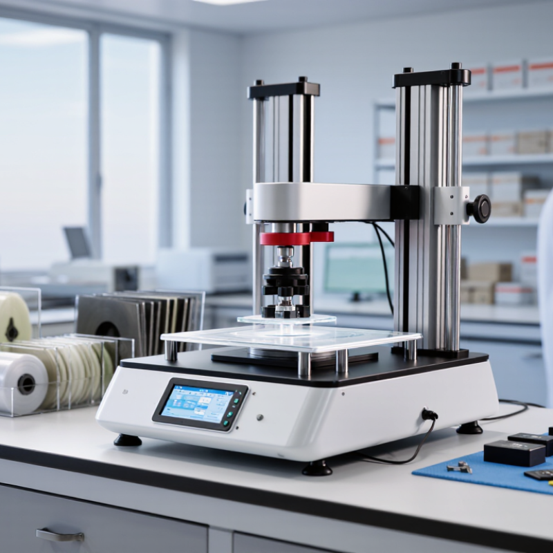
Choosing the best Cof Testing Equipment in 2026 is not a simple shopping decision. The right system must measure static and kinetic coefficients of friction with repeatable results. In packaging, a small reading difference can affect film feeding, stacking, sealing, and machine speed. A test that looks precise may still mislead when samples carry dust, moisture, or uneven coatings. Real conditions matter.

This guide examines equipment through practical laboratory requirements, not marketing claims. It considers load-cell stability, sled design, travel control, software traceability, calibration support, and operator safety. Compliance with recognized methods, including ASTM D1894 and ISO 8295, should be verified against your exact material and testing purpose. Good instruments also make daily work easier: clear fixtures, controlled conditioning, simple data export, and serviceable components save time. Yet no machine removes every source of variation. Even experienced technicians can produce different results when conditioning or surface alignment changes. That weakness deserves attention.

The best choice may be a robust mid-range tester, not the most expensive model. Before buying, compare uncertainty, repeatability, technical support, and total ownership cost. Ask whether the supplier can provide traceable calibration records and application guidance. This article offers a balanced framework for that evaluation. It does not promise one universal winner, because films, papers, coatings, and medical materials demand different priorities. Start with the measurement you must trust.

What Is the Best COF Testing Equipment in 2026?

COF Fundamentals: Static and Kinetic Friction in ASTM D1894 Testing

What Is the Best COF Testing Equipment in 2026?

The best COF tester measures static and kinetic friction separately. This distinction matters in packaging, films, labels, and sliding components. Static COF describes the force needed to start movement. Kinetic COF describes resistance during steady motion. ASTM D1894-14(2022) uses a 200 g sled and a test speed of 150 mm/min. It records the first force peak, then evaluates the moving force. ISO 8295 follows a similar measurement principle.

A capable system should control speed, sled load, travel distance, and specimen alignment. It should also capture force curves, not only final coefficients. A sharp peak may reveal blocking between film layers. A drifting kinetic value may indicate surface migration, humidity, or contamination.

Testing at 23 ± 2°C and 50 ± 5% relative humidity follows common conditioning practice referenced through ASTM methods. Small environmental changes can alter results.

In practical laboratory work, five or more specimens can expose variation between samples. Test both material directions when orientation matters. A neat number can still mislead. I have seen acceptable averages hide one unstable film edge. That is why repeatability, calibration records, and raw force data deserve equal attention. The equipment should make these checks easy, even when the operator is tired or the sample preparation is imperfect.

ASTM D1894 vs ISO 8295: 200 g Sleds and 150 vs 100 mm/min

What Is the Best COF Testing Equipment in 2026?

The best COF testing equipment should support both ASTM D1894 and ISO 8295. These methods appear similar, but their test speeds differ. Both commonly use a 200 g sled, creating a practical comparison point. ASTM D1894 typically uses 150 mm/min. ISO 8295 generally uses 100 mm/min. That difference can change the measured static and kinetic coefficients of friction, especially with thin films or treated surfaces.

A reliable tester needs a calibrated load cell, stable sled movement, and accurate speed control. The sled must remain level and contact the specimen consistently. Film direction also matters. Machine direction and transverse direction may produce different results. Conditioning temperature and humidity should be recorded. A common mistake is comparing results from different standards without reporting the speed. The numbers may look close, but the test conditions are not identical. I have found that repeatability can suffer when operators rush specimen alignment.

Tips: Choose equipment with selectable speeds of 100 and 150 mm/min. Confirm the sled mass before testing. Clean the contact surfaces carefully, but avoid changing their texture. Run repeated measurements and inspect unusual values instead of deleting them immediately. Sometimes, the “bad” result reveals a setup problem. Calibration records should include the load cell, travel speed, sled mass, and test date.

Core 2026 Specifications: 0.001 COF Resolution and 0.01–10 N Loads

What Is the Best COF Testing Equipment in 2026?

The best COF testing equipment in 2026 should offer fine measurement and controlled force. A 0.001 COF resolution can reveal small surface changes that ordinary instruments may miss. The 0.01–10 N load range also supports delicate films, coated papers, packaging layers, and textured materials. Low-force testing needs stable sensors, smooth sled movement, and careful alignment. In practical laboratory work, uneven samples often create larger errors than expected. That detail is easy to overlook.

Reliable equipment should provide repeatable results, clear software records, and traceable calibration options. Operators should verify the load cell before testing unfamiliar materials. The test speed, contact area, temperature, and humidity also need control. Otherwise, a precise display may create false confidence. I would not choose a system based on resolution alone. Mechanical stability matters just as much. A useful instrument should show raw data, repeated runs, and visible variation between specimens.

Tips: Use several specimens instead of one. Record conditioning time before testing. Check whether the instrument maintains accuracy near 0.01 N and across the full 10 N range. Clean the sled carefully, but avoid changing its surface condition. Run a blank check before important measurements. Small setup differences can shift the COF result. That is worth reviewing.

Best COF Equipment for Films, Paper, Textiles, and Packaging

In 2026, the best coefficient of friction (COF) tester is not simply the fastest instrument. It must match the material, surface finish, and production question.

For films and flexible packaging, choose equipment that measures static and kinetic COF with controlled speed and pressure. A smooth sled, stable sensor, and low-friction guide can reveal differences between seal layers.

For paper, repeatable contact pressure matters because fibers may compress unevenly. In textile testing, adjustable fixtures support woven, knitted, and coated surfaces.

Reliable results start with disciplined preparation. Condition samples under documented temperature and humidity, then test machine and cross directions when relevant. Calibrate force and distance systems regularly. Record sled mass, travel speed, dwell time, and sample age.

Experienced technicians also inspect contamination, wrinkles, and edge damage. Procedures aligned with applicable ASTM or ISO methods improve comparability.

One method rarely fits every case. That limitation is easy to overlook.

I still allow extra replicates when results seem unusually perfect.

Tips:

Select a test range that reflects actual handling, not only laboratory convenience. Use reference materials between projects to detect instrument drift. Keep raw curves, not just average COF values. A single average can hide stick-slip behavior. Ask whether humidity changed the result. It often does. Before purchasing, request demonstrations using your own films, paper, textiles, or packages, and compare repeatability, software traceability, fixture changes, and operator workload.

2026 Selection Criteria: Calibration, Repeatability, Automation, and Data Records

The best COF testing equipment in 2026 should prove measurement quality, not merely display a friction curve. ASTM D1894 specifies controlled sled movement near 200 mm/min. ISO 8295 uses a different operating condition, commonly 100 mm/min. Therefore, laboratories should select equipment that supports the required method, film type, load, and sliding speed. A convenient default can produce misleading comparisons.

Calibration records deserve equal attention. ISO/IEC 17025 expects traceable calibration and documented measurement uncertainty. NIST Technical Note 1297 explains expanded uncertainty with coverage factor k=2, representing approximately 95% coverage. The software should preserve calibration dates, reference standards, operator identity, and environmental readings. Temperature and humidity matter. A warm polymer film may behave differently from one tested after conditioning overnight.

Repeatability is more than a low standard deviation. ISO 5725-2 distinguishes repeatability from reproducibility, so laboratories should test both within-run and between-operator variation. Automation should control specimen alignment, preload, travel distance, and stop timing. It should not remove human review. That sounds obvious, but misaligned samples still create attractive, unusable graphs. Look for raw-data export, audit trails, version history, and locked method settings. I would also challenge one assumption: more decimal places do not mean better accuracy. A stable instrument with transparent records is often more valuable than a faster system with impressive dashboards.

What Is the Best COF Testing Equipment in 2026? - 2026 Selection Criteria: Calibration, Repeatability, Automation, and Data Records
Selection Criterion Evaluation Dimension Recommended 2026 Selection Target How to Verify Before Purchase Why It Matters for COF Testing
Calibration Load-cell calibration traceability Current calibration certificate
Traceable to recognized national or international standards; calibration points should cover the intended test-load range.
Review the calibration certificate, reference standards, calibration date, uncertainty, and stated measurement range. A COF result depends directly on accurate normal-force and friction-force measurements. Calibration outside the working range can create systematic error.
Calibration Force resolution and capacity Select a force range suitable for the specimen and method. A practical target is resolution of at least 0.1% of full scale or better. Compare the force sensor capacity, resolution, accuracy specification, and expected friction force for the test materials. An oversized sensor may reduce useful resolution, while an undersized sensor can overload or distort the measurement.
Calibration Travel and speed calibration The instrument should verify test speed and sliding distance against the selected method, including ASTM D1894 or ISO 8295 when applicable. Request a speed-verification record and confirm that the software records actual or verified speed, distance, and test duration. COF can change with sliding speed and distance. Controlled motion improves comparability between specimens and laboratories.
Repeatability Within-run variation For a stable, homogeneous reference material, establish an internal acceptance limit such as coefficient of variation of ≤5%, subject to method and material behavior. Run at least five replicate measurements under identical conditions and review the mean, standard deviation, and coefficient of variation. Repeatability indicates whether the equipment and test procedure can produce consistent results under the same operating conditions.
Repeatability Between-day stability Use a control specimen and define a laboratory-specific control range from historical data; investigate meaningful drift before releasing results. Test the same control material on different days, with different operators where possible, and compare control charts. Long-term stability helps distinguish real material changes from instrument drift, environmental effects, or operator variation.
Repeatability Specimen alignment and contact control Use a rigid, level specimen table, defined contact geometry, controlled normal load, and a documented sample-conditioning procedure. Inspect fixtures and leveling controls; confirm that the method specifies specimen size, contact area, conditioning, and applied load. Misalignment, wrinkles, contamination, and inconsistent contact pressure can produce larger variation than the sensor itself.
Automation Programmable test sequence Automated control of conditioning, normal loading, dwell time, sliding speed, sliding distance, return motion, and repeat count. Review a live software demonstration and confirm that each method parameter can be locked, saved, and recalled. Automation reduces operator-to-operator differences and helps ensure that every specimen follows the same test sequence.
Automation Pre-test and post-test safeguards Include overload protection, travel limits, emergency stop, door or guard interlock where applicable, and automatic zero verification. Ask for a safety-function demonstration and review alarm behavior, recovery procedures, and user-access permissions. Safety controls protect operators, specimens, fixtures, and force sensors while preventing invalid runs caused by setup errors.
Data Records Raw-data capture Record time or distance, normal force, friction force, calculated static COF, calculated kinetic COF, and environmental conditions when required. Export a sample data file and confirm that raw channels, units, sampling settings, calculation rules, and test identifiers are included. Raw data allows results to be independently reviewed and calculations to be repeated without rerunning the specimen.
Data Records Audit trail and electronic signatures User roles, time-stamped changes, method version control, result approval, and protected original records. Check whether the system records who created, changed, reviewed, and approved a method or result. Controlled records support laboratory quality systems, investigations, traceability, and regulated workflows.
Data Records File formats and backup Export to non-proprietary formats such as CSV or PDF, with automatic backup and clear file naming based on sample ID and test date. Perform a complete export and restore test; confirm that files remain readable without specialized software. Accessible and recoverable data reduces the risk of losing results and supports integration with laboratory information systems.
Method Compliance Applicable standards Support the laboratory’s required method, commonly including ASTM D1894 for plastic film and sheeting or ISO 8295 for plastics film. Compare the instrument’s controllable parameters, fixture dimensions, force range, and reporting fields with the current edition of the required standard. A technically capable instrument is not sufficient if it cannot reproduce the required method conditions and reporting requirements.
Environment Temperature and relative humidity control Provide a documented conditioning environment appropriate to the selected method; record actual temperature and relative humidity when required. Check the conditioning specification, sensor calibration, environmental logging, and specimen equilibration time. Surface moisture, temperature, and humidity can significantly affect friction, especially for polymer films, paper, coatings, and treated surfaces.
Serviceability Verification and maintenance workflow Provide documented zero checks, reference-material checks, preventive maintenance, software updates, and recalibration intervals. Review maintenance instructions, service records, spare-part availability, and the procedure for handling failed verification checks. A repeatable verification routine helps maintain measurement confidence throughout the equipment’s service life.
Overall Selection Best-fit decision rule Choose the system that meets the required method, demonstrates calibration traceability, achieves acceptable repeatability, automates critical steps, and preserves complete raw data. Use a documented qualification protocol with reference materials, replicate tests, data-export checks, and user-acceptance testing. The best COF equipment is the system that produces defensible, repeatable, and traceable results for the laboratory’s actual materials and workload.
Note: Acceptance limits should be confirmed against the current edition of the applicable test method, the material being tested, and the laboratory’s own validation data. ASTM D1894 and ISO 8295 may specify different apparatus, conditioning, and reporting requirements.